Curve boards
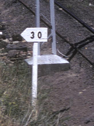
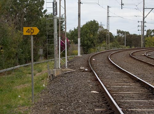
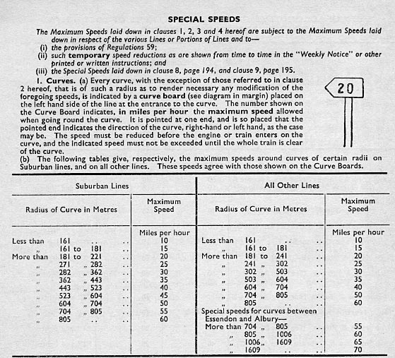
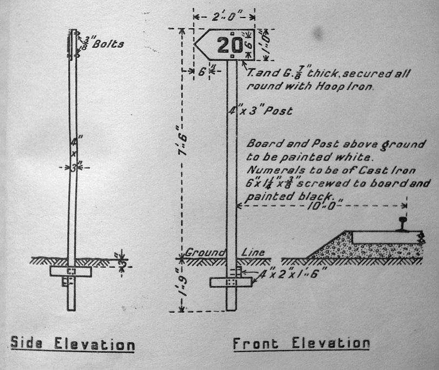
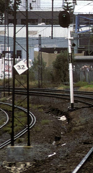
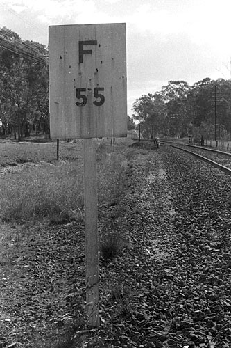
| Curve boards are a common sight all over the system and are placed at the entrance to a curve whenever a curve is sharp enough to require a speed lower than the maximum track speed. Before metric conversion curve boards were white with black numerals, MPH (lower left photo) in the early 1980's curve boards got metric speeds, km/h (lower right photo) which are indicated by black numerals on a reflectorised yellow background. As noted in the WTT extract, curve speeds only apply until the train exits the curve. Unlike many other railways, Victoria has never used signs to indicate the maximum speed for a section. | |||||
 |
 |
||||
 |
|||||
|
|||||
 |
|||||
Gradient boards
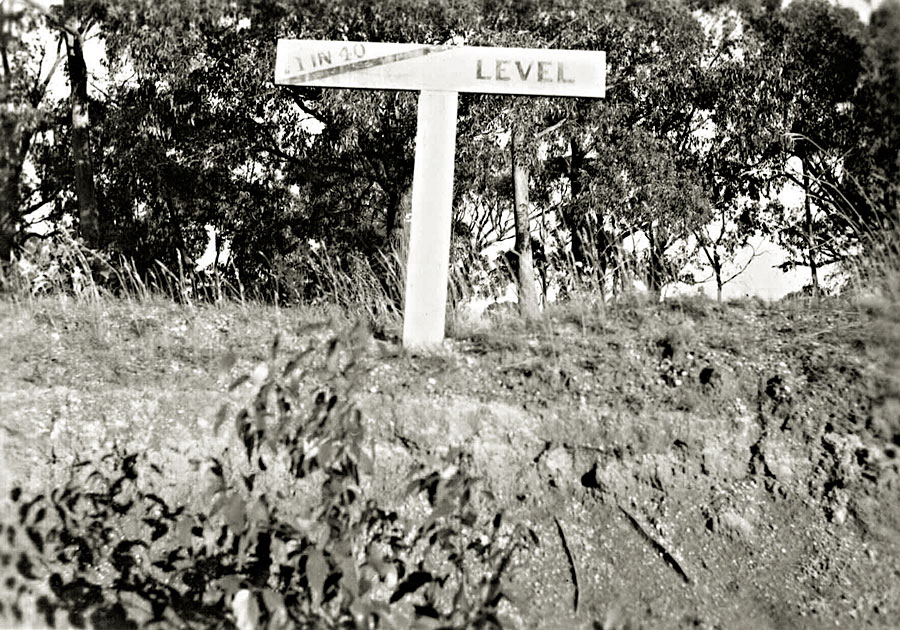
| Gradient boards disappeared long ago, this is the only photo that I know of that shows one. They showed the crew the point at which the gradient changed and what the gradient was. This photo is believed to have been taken at Mount Helen on the Buninyong line, June 1940 by Wal Jack |
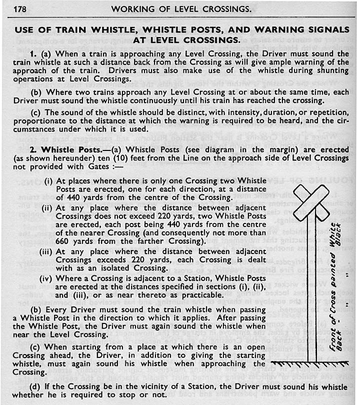
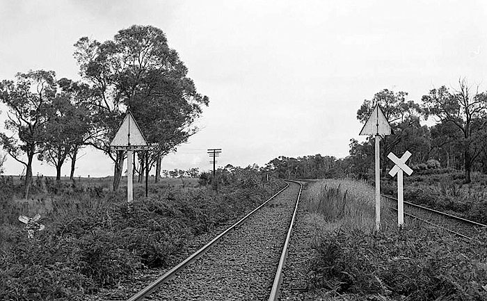
Whistle posts
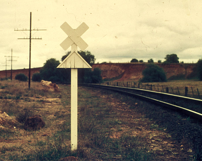
| Whistle posts are used to indicate to a driver that he is approaching a level crossing and must act in accordance with the instructions shown below the diagram. Level crossings equipped with interlocked or hand gates did not normally have a whistle post as it was not neccesary to whistle for these crossings. There were a few locations where whistle posts were erected prior to a curve in a cutting. |
 |
 |
|||||||
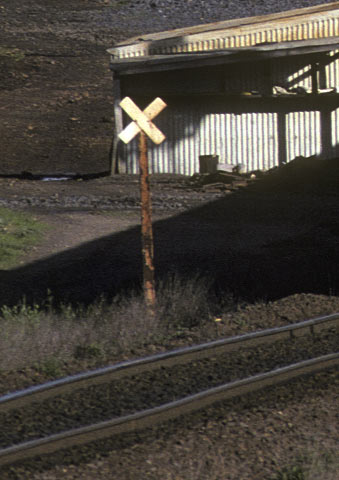
| A standard whistle post at Bacchus Marsh, 1988. They are normally placed on the left hand side of the track.The backs of whistle boards are painted black. | ||||||||
|
CLICK HERE FOR
DIAGRAM OF WHISTLE POST |
||||||||
 |
 |
|||||||
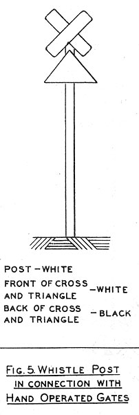
| These whistle posts were erected prior to a level crossing equipped with hand gates. The only "official" reference I have ever found for these whistle posts is in a VRI permanent way correspondence course book. Presumeably a train whistling at this post alerted the gatekeeper to the trains presence. Although I have no official documentation to prove it I suspect that it also informed the crew that they needed to lookout for the gates and be able to stop if the gates were not swung. It would be interesting to know if they were ever used on higher speed tracks, I suspect not! This post was on the down between Parwan and Bacchus marsh and was removed by 1977. | ||||||||
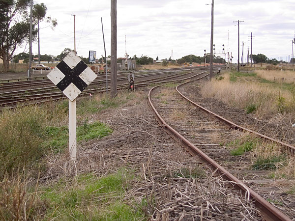
"Approach Section Indicator" boards and "Stop Boards"
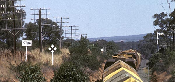
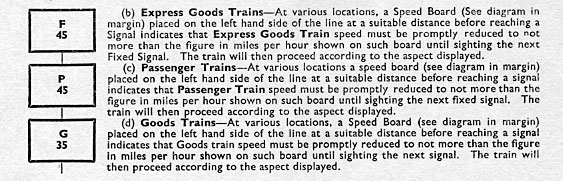
| At certain locations, "bank engines" were employed to push trains out of a station. At the top of the grade, Stop boards were used to indicate the point to which the bank engine was authorised to operate to. The board was as shown in the photo, a white board with the word "STOP" in black letters
Approach section indicator boards indicated the point at which wig wags, flashing lights or boom gates would activate, (see the General Appendix ammendment below) The Approach section indicator board was a white diamond with a black X) as shown below. |
|
Photo of the "stop" and "approach section indicator" boards at MP 148 miles 57 chains, up side of Stawell. Up trains from Stawell faced approx 1 mile of 1 in 50 grade
photo date 1982 |
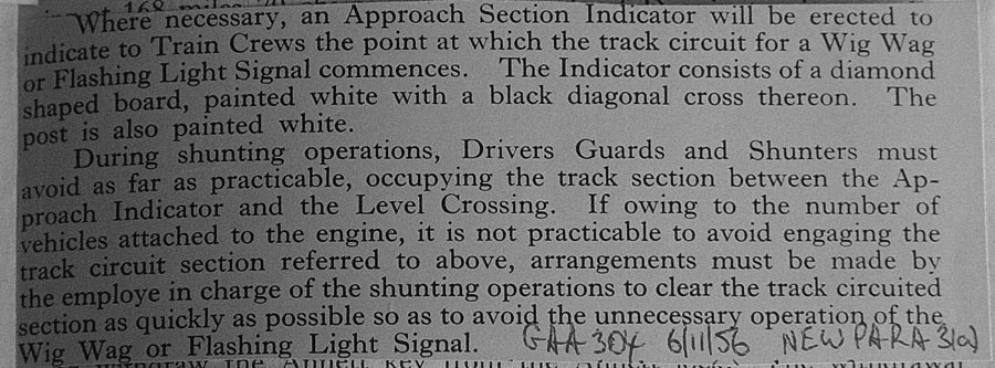
General Appendix ammendment courtesy Peter J. Vincent
|
The "approach section indicator board" at Somerton. A driver could pull up to the dwarf signal but this would activate the booms at Somerton road. If a driver does not pass the board the booms will not be activated. photo date 2006
|
Location boards
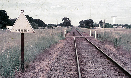
| Location boards were often provided at locations without a distant signal, or at locations without fixed signals, to indicate to the driver the approach to a station. They were generally about 400 yards prior to the station. |
Two lines approached Nyora from the east, on the left the Wonthaggi line and on the right the Korumburra/Yarram line.
Nyora didn't have any distant signals so was provided with location boards 442 yards from the home arrival signal, (SEE DIAGRAM)
Photo circa 1975, courtesy Peter J Vincent
Catch point boards
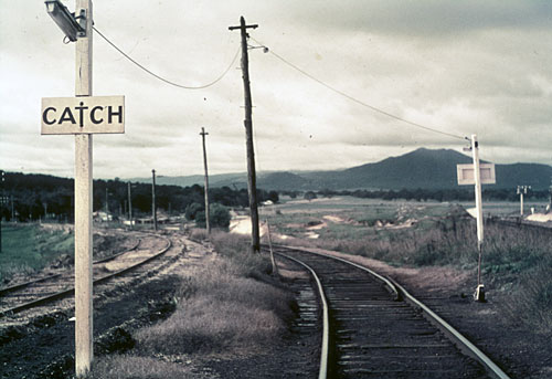
| Catch point boards were provided to indicate the presence of catch points. Catch points were provided to purposely derail a vehicle in order to protect a running line or other area, in this case the catch point protected against a vehicle running away from the Ararat yard into the locomotive depot area. Photo is of the track leading from Ararat yard to the loco depot, circa 1970. |
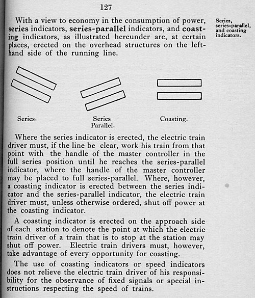
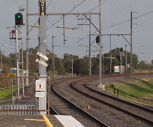
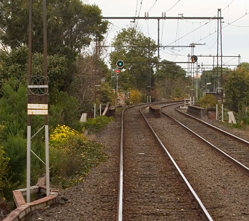
Coasting or Shut off boards
 |
 |
||||
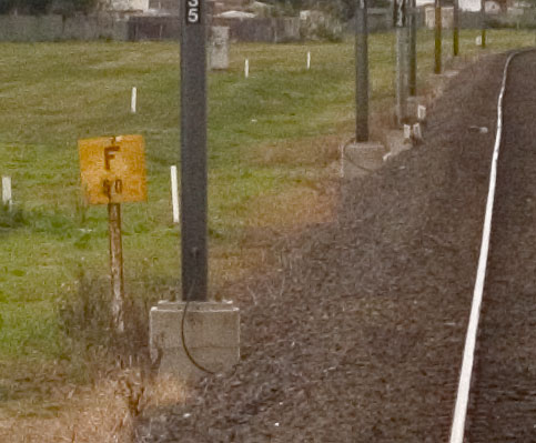
| It appears that "shut off" boards were used very soon after electrification was introduced, quite possibly they were introduced when electrification started. The series boards shown above, told the driver not to power past the series position on the electric train master controller. In this case a slow speed was required for the sharp curves between Merri and Rushall. The "coasting" or "shut off" board below told the driver that after powering from the previous station that he was to shut off power at this point and coast to the next station. It is important to remember that until the introduction of Harris trains in 1956, suburban trains were not equipped with speedometers. | |||||
 |
|||||
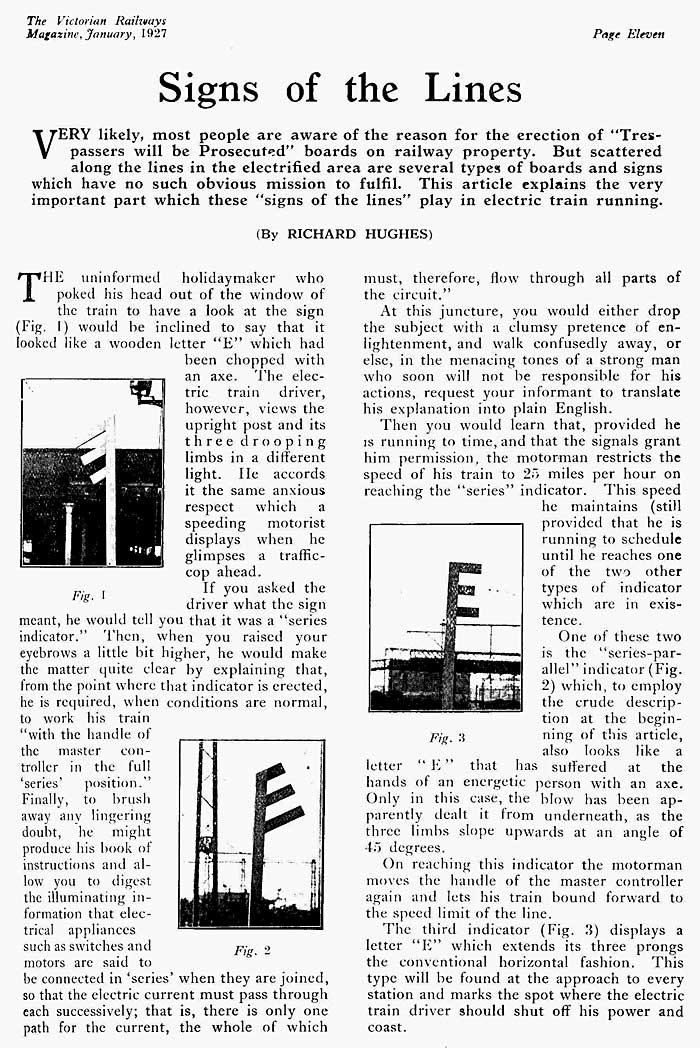
| The article below comes from the Jan. 1927 Victorian Railways magazine. It describes the original coasting boards with three prongs. I am unsure when this style was replaced with the later type shown above, perhaps when the Harris boards, descibed below, were introduced? | |||||
 |
|||||
 |
|||||
Harris train Shutoff boards
 |
|||
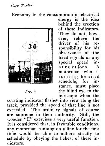
| A refinement of the original coasting board was introduced when the Harris trains were introduced in 1956. These boards indicated the speed that a driver needed to power to, in this case 32 MPH, the driver upon reaching this speed would shut off and roll to the next station whilst keeping the timetable | |||
Speed boards
Up approach to St. Albans.
 |
|
||
Vehicle boards
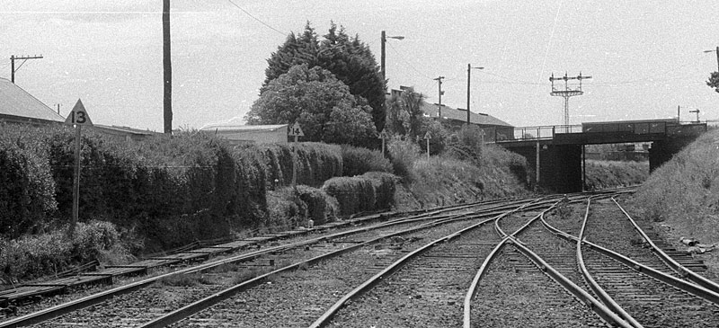
| In the days before radio communication the railway relied on hand signals for signalman, station staff and guards to communicate with the driver. These vehicle boards, at Ballarat, told the driver where to stop without the signalman at Ballarat B box having to relay the hand signals from the station staff night after night to the drivers of the down Overland and down Vinelander. The 13 board was where to stop a 13 car passenger train, the 14 board where to stop a 14 car passenger train and so on. Another location that had similar boards was between Kensington and Newmarket. |
Terminal stop boards
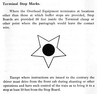
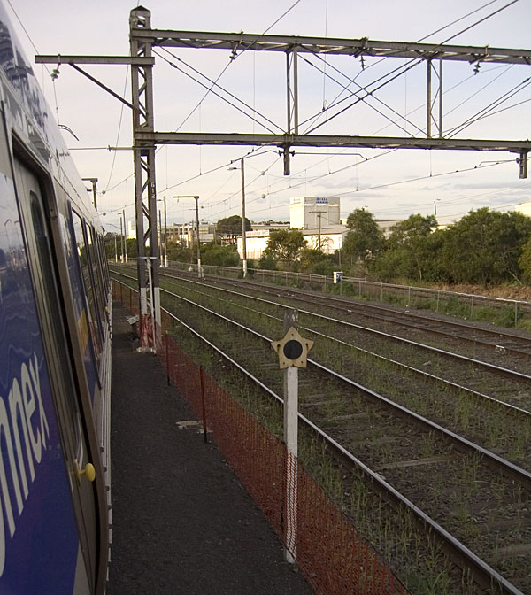
Terminal stop board at Broadmeadows, 2006
Test brake boards
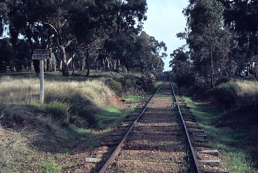
|
At locations situated at the bottom of steep grades a brake test board was often provided, this indicated to the driver that a running brake test was to be
performed prior to decending into the station. Photo at Wedderburn May 1980 Photo courtesy Chris Elliot |
Siemens boards
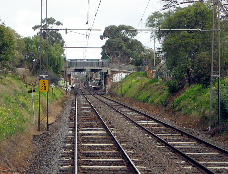
| Due to ongoing braking problems with Siemens suburban trains a 30 km/h speed limit was applied for any station where an automated road or pedestrian crossing was within 100 metres of the platform, this was to apply a safety margin in case of platform overshoots. The boards appeared in 2009. |