Electric Staff
As used by the Victorian Railways
Article written by Chris Wurr.
Single lines presented a serious safety issue for railways because trains running in both directions used the same track and the resultant possibility of a head on collision without procedures for ensuring only one train could be using the track at any one time.
Arthur Moore Thompson (born 1852) became the Signal Superintendent of the London & North Western Railway on 1st January 1882, following his previous ten years as the Signal Department’s Head Draughtsman. He was aware of the drawbacks of the Tyer’s Tablet system of single line safeworking which had been installed on a few of the company’s lines, and set out to devise a not dissimilar, but more adaptable system for the L&NWR.. The result was Electric Train Staff, known simply as Electric Staff on the Victorian Railways. In conjunction with L&NWR’s Chief Mechanical Engineer Francis William Webb, Thompson’s Electric Train Staff system was patented in England in 1888. The system proved (for the L&NWR at least) to be a more flexible alternative to Tyer’s Tablet and was installed on much of their system. Railways other than the L&NWR showed interest in it, but because it was invented under the auspices of the L&NWR, they were unable to on-sell the equipment to other railways. Consequently a licence was granted to the Railway Signal Company and from this humble beginning, Electric Staff proliferated to many English and colonial railways. Electric Staff adoption spread to every state and commonwealth railway in Australia in due course. In Victoria, it was a structural weakness in the Moorabool viaduct on the Geelong – Ballarat line, which necessitated the previous double line to be singled. Tyer’s Tablet had been put into service only 17 months before on the section Moorabool -- Gheringhap, but this was superseded by Webb & Thompson’s Electric Train Staff starting on 21st April 1897. The double line was singled to prevent two trains crossing the viaduct at the same time. Thus began the enduring love affair of Electric Staff on the Victorian Railways. E.S. spread over the years to all single main lines, many secondary lines and even to heavily trafficked branch lines.
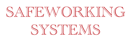
LARGE ELECTRIC STAFF.
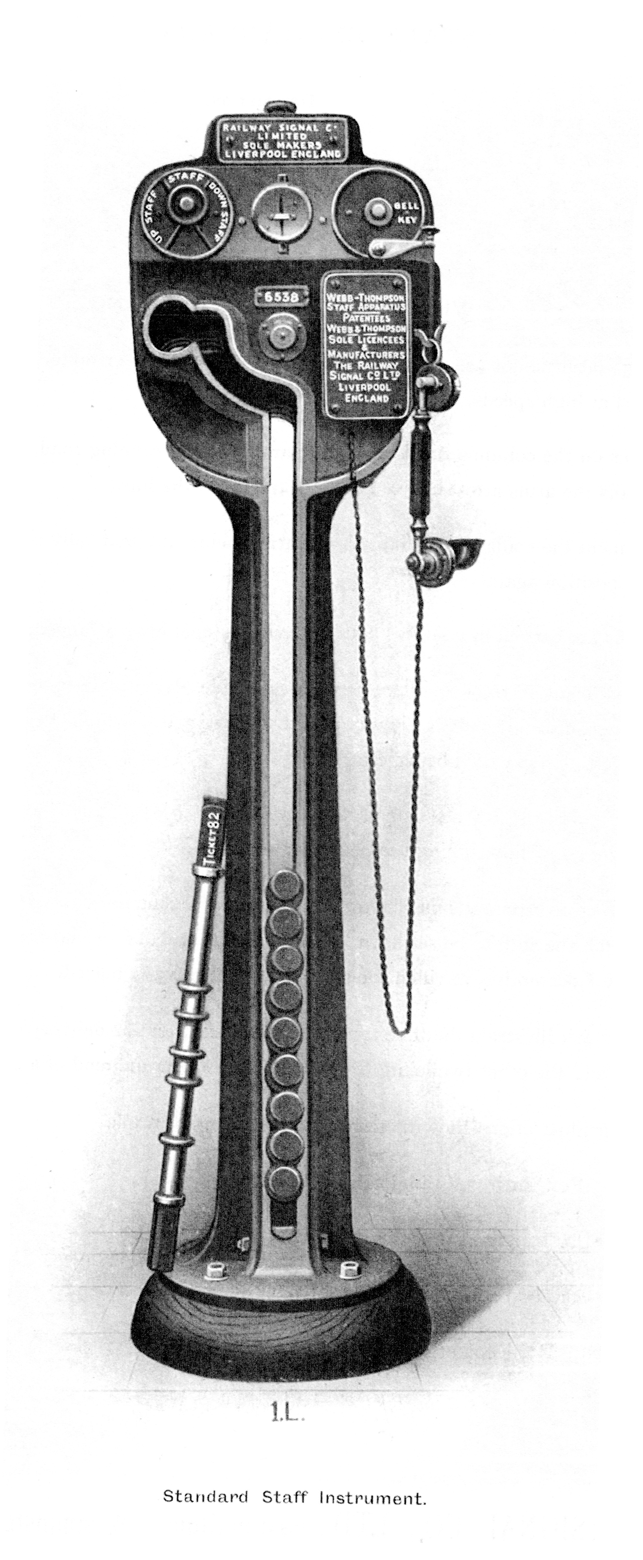
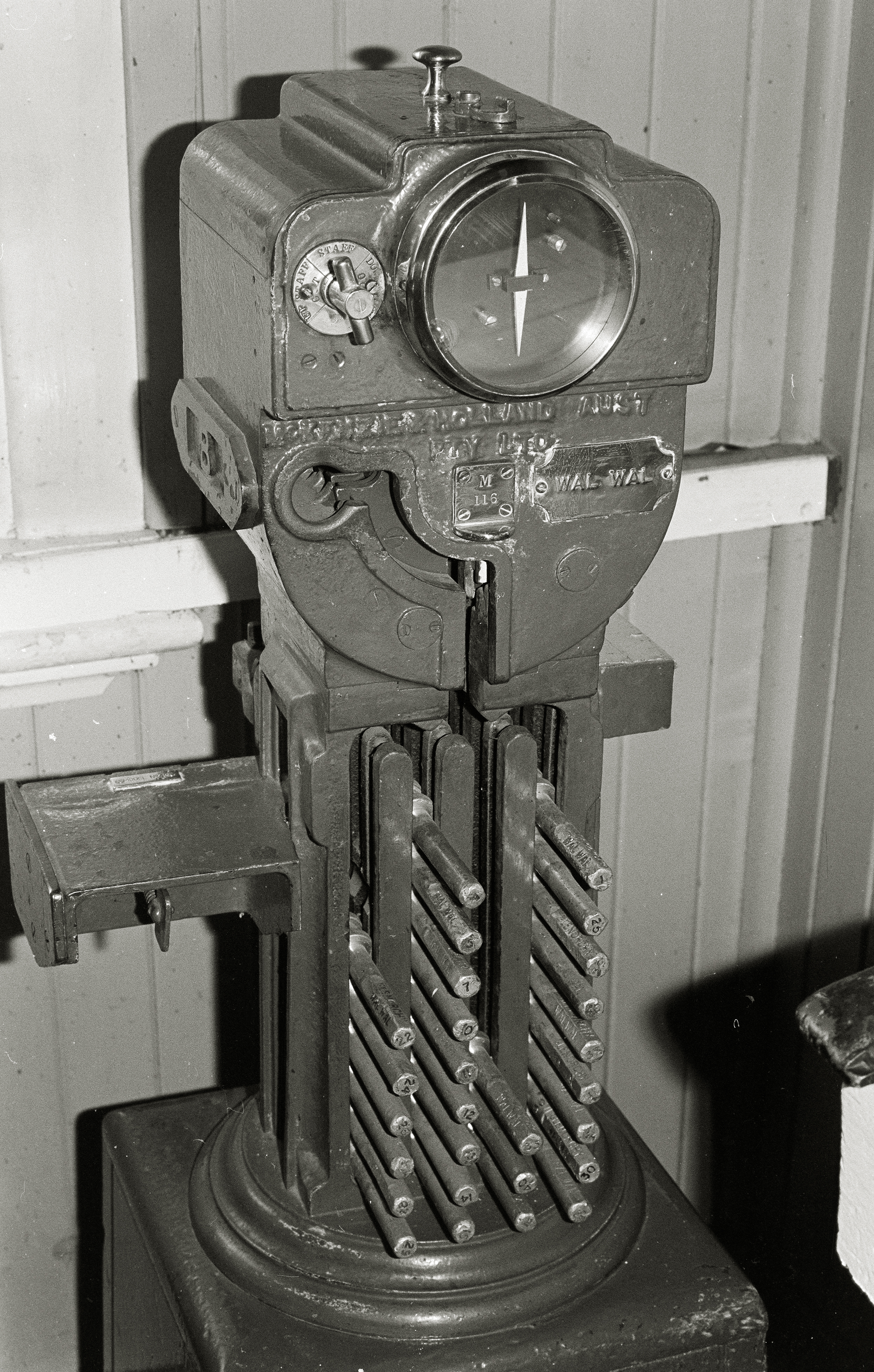
ABOVE: Large electric staff instrument, note, to my knowledge, VR neversingle column staff instruments.
ABOVE: The staff instrument at Traralgon for the single line section to Rosedale.
On the V.R., Electric Staff instruments used originally were the large type. A Large Electric Staff instrument is a heavy cast iron pedestal comprising the head through which the staffs are inserted or withdrawn, an indicator for Staff In/Staff out, a Bell/Staff switch, a bell tapper key and a galvanometer which shows current flow. Inside the head of the instrument is a vertically rotating drum which is locked or unlocked by means of electrically-operated locks. Bolted to the rear of the head, is a slotted guard to ensure that only the correct pattern of staff is inserted into that particular instrument. Below the head are the two cast iron columns for receiving incoming staffs and storing them. The complete instrument was bolted to the floor of the Signalbox and stood 4’ 9¼” tall.
OPERATION. The system works by means of instruments at each end of the block section which are connected by line wires to conduct an electrical current between the two. If a train is required to run from A to B, the Signalman at A will Call Attention to the Signalman at B. The Signalman at B will repeat the one beat Call Attention Signal. A will then ask for a staff for the train (using a code of bell signals identical to Double Line Block to identify what sort of train is being offered). If B is in a position to accept the train, he will repeat the bell code and on the last beat, will hold the bell key down. This allows current to flow from B to A and the galvanometer needle on both instruments will deflect, unlocking the locks in the head of the instrument at A. Signalman at A will now turn his Bell/Staff switch to the For Staff position and withdraw a staff through the drum of the instrument. This movement through the drum mechanically resets the indicator to For Bell. A then holds the pointer of the left hand switch down in either the Up Staff Out or Down Staff Out position and this action stops the deflection of the galvanometer needle on B’s instrument, thus visually showing the B Signalman that the staff has been withdrawn at A. The B Signalman also turns his left hand indicator to Up/Down Staff Out as a reminder. The staff is then given to the Driver as authority for his train to be in the section between the two block stations engraved on the staff. The reason for the movement of the right hand Bell/Staff indicator was to prevent depletion of the batteries which operate the system. The normal position of the switch was For Bell. The operation of this switch was subsequently automated. In later years, many instruments were converted to magneto operation and thus the Bell/Staff switch was not required and therefore removed from those instruments. When the train departs A, the Signalman there will send B the Train Departure Signal (two beats). B will acknowledge by repeating. When the train has arrived complete at B, the Signalman there will receive the staff from the Driver, view the rear of the train to ensure it is complete and then “sink” the staff in the instrument and bell Train Arrival (three beats) to the Signalman at A. A repeats the three bells. The staff indicators will be turned to the Staff In indication to remind both Signalmen that there is no staff out of either instrument. Signalmen cannot sound the bell of his own instrument --- only that at the opposite end of the sections he works with. The withdrawal of a staff from an instrument locks both instruments at each end of the section until the withdrawn staff is inserted back into one or other of the instruments. This was one of the drawbacks (initially) of Tyer’s Tablet --- a withdrawn tablet had to be inserted into the machine at the opposite end of the section. It could not go back into the machine it had come out of. The drum in the head of Electric Staff instruments is painted in quarter segments visible to the operator. Removing or inserting a staff, rotates the drum 90°. The segments are alternately red or white and these segments indicate to the employees whether the instruments at each end of the section are “In Phase” or “Out of Phase”. For a staff to be withdrawn, both instruments have to be “In Phase” i.e. the phases at both ends of the section have to be red or white. If one is red and the other white (or vice versa) a staff cannot be withdrawn. After withdrawal, they will be “Out of Phase”, with the segment at one end of the section, being different to the one at the opposite end. This is another means to identify any problems encountered, where for some reason a staff cannot be withdrawn. With the instruments being “Out of Phase” a staff cannot be withdrawn from either end. MINIATURE ELECTRIC STAFF. Many railways in the United Kingdom and its dominions, whilst embracing Electric Staff, disliked the physical size of the Large Electric Staff and its apparatus, and so the Railway Signal Company set about making a smaller version. The result was Miniature Electric Staff being invented in 1906. M.E.S instruments are 2’ 4” tall --- half the height of an L.E.S. job! M.E.S later came in two types --- M style and S style. S style is of slightly smaller physical size than M. The Victorian Railways only adopted the M style. On 3rd September 1912, the V.R’s. first sections of Miniature Electric Staff commenced service between Buangor – Dobie – Ararat A on the busy Western Line. M.E.S. operates in exactly the same way as L.E.S. In fact the block rules for Electric Staff do not differentiate between the two. The adoption of M.E.S on heavily trafficked and fast lines throughout the state, enabled the commencement of automatic exchanging of staffs between trains and Signalmen via apparatus on the ground and fitted to locomotives. This invention obviated the need for trains to slow down to enable staffs to be exchanged manually between Fireman and Signalman. Now, through trains could achieve the same at speeds up to 60 mph.
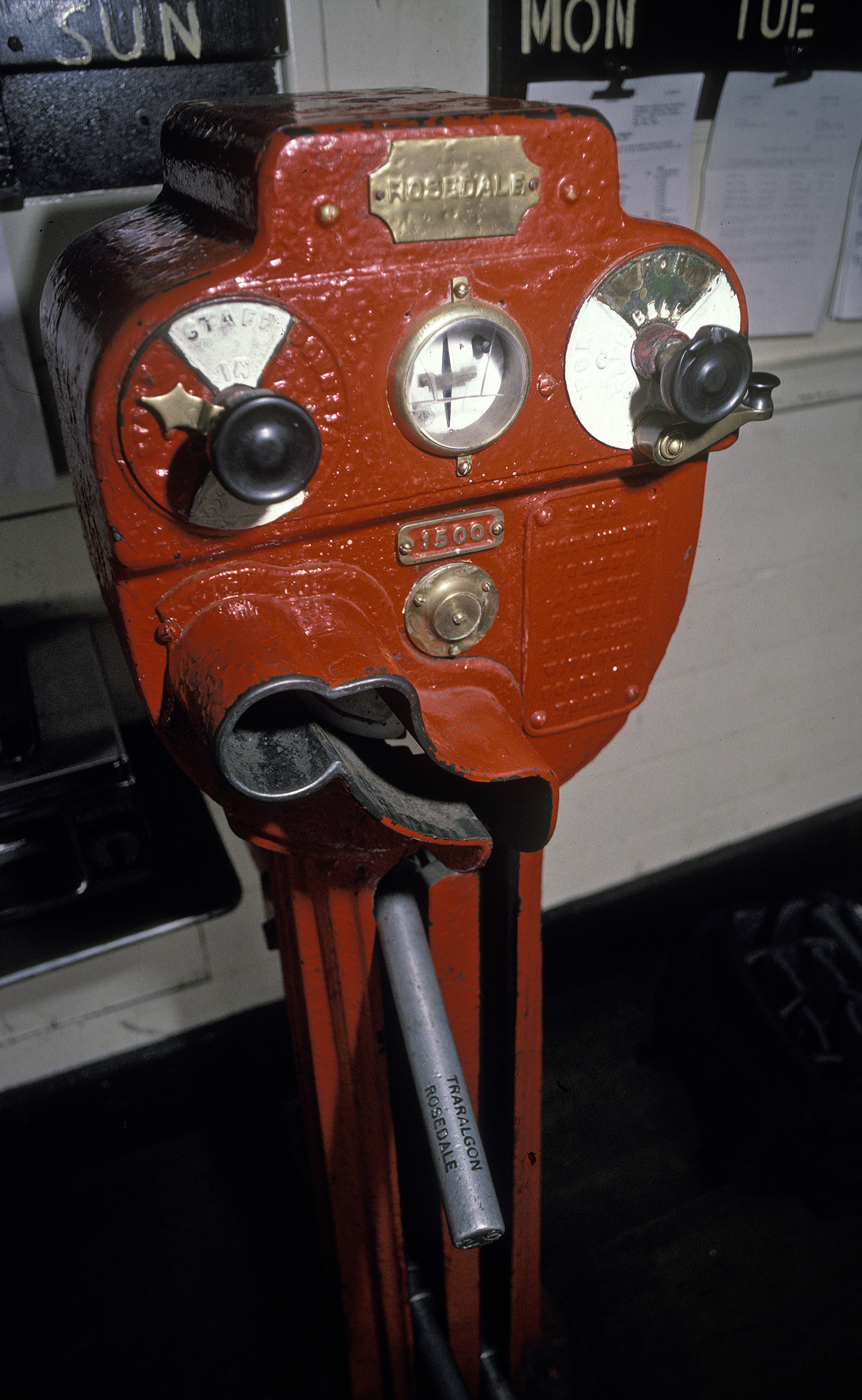
DESCRIPTION OF STAFFS. Large Electric Staffs are constructed using a 1¼” diameter rod measuring 23” in overall length. Four 2” diameter collars are fixed at precise measurements on the rod and these are what hold the staffs secure in the columns of the instrument. A gauge (or pattern) ring is also fixed on the rod and its position varies depending on which of four patterns the staff is. The position of this gauge ring is what prevents a staff of the wrong pattern from being inserted into an instrument. The gauge ring requires to pass through the slot in the guard bolted onto the rear of the head of the instrument. Large Electric Staffs came in four patterns. Continuing a slight variation of the tradition of four patterns of Train Staff used in the Train Staff & Ticket system of safeworking, the patterns were nominated as colours, viz White, Red, Blue and Green pattern. At the gauge ring end of the staff, the rod was machined out and fitted with a ¼” wide nib called a “feather”. Feathers were fitted into different quarters of the machined slot in the end of the staff in accordance with what pattern the staff was. The feather engaged the locks used on staff locked points, staff exchange boxes and switching instruments. Thus only the correct pattern staff could be used in these devices. At the opposite end of the staff to the lock, the names of the two locations between which the staff applies, are engraved one above the other. The upper name is always the Up end of the section, i.e. the location nearer to Melbourne. Also on that end of the rod, was engraved the number of the staff. Early Large Electric Staffs were made of mild steel with brass collars and rings attached to the main rod. Later staffs were turned up on lathes using Duralumin, an aluminium-copper alloy (Duralium if you are from the United States!) Duralumin staffs weigh about 3 lb 7 oz, so it is easily seen why M.E.S. was advocated for. Miniature Electric Staffs comprise a main rod of 5/8th” diameter and 10 5/8th” length. Four collar rings of 1 1/8th” diameter and of two different thicknesses are spaced along the staff. Arranged in differing positions are two gauge rings of ¾“ diameter. Refer to illustrations for clarity of this description. At one end of the staff are two flat angles upon which are engraved the names of the section to which the staff applies. As with L.E.S., the “Up” station is above the “Down. The number of the staff is engraved on the end of the main shaft adjacent to the section names, a well as on the top between the last collar and the section names. This type of staff was available in six different patterns --- A to F, although with one exception in Victoria, F pattern was not used. The pattern letter of the particular staff is engraved into the opposite end of the shaft from the names. M.E.Ss. do not have a lock device in one end as with the L.E.S. The whole of the staff acts as the means to unlock and lock staff locked points, using a Miniature Staff Lock sometimes known as a Drawer lock. The miniature version of staff was initially a one-piece turned down mild steel device. These weighed about 12½ oz and being of steel, they were chrome-plated to inhibit rust. Over the years with constant use, the chromium flaked off and dropped into the mechanisms of the instruments and caused failures. They were replaced mostly with identical staffs turned up from Duralium alloy. These weigh only about 6½ oz. The reason for different patterns of staffs was so that there could not be two instruments in the one signalbox, working two different block sections AND being of the same pattern. This obviated the potential problem that a staff could be accidentally inserted into the wrong machine. Yet another safety feature of the whole system.
ADDITIONAL IMPROVEMENTS BROUGHT ABOUT BY ELECTRIC STAFF.
The flexibility brought about by the introduction of Electric Staff may not have been realised by V.R. management at the time. However “accessories” to the basic system were devised by the Railway Signal Company as the years went by and the V.R. embraced most of them over time. Improvements adopted by the V.R. include: Automatic exchanging of Miniature Electric Staffs between Signalmen and Engine Crews at speed. Automatic operation --- two types. Composite Electric Staff working. Divided Electric Staff working. Pilot Staff working. Bank Engine Key. Staff locking of points at intermediate sidings. Intermediate Electric Staff instruments. Switching instruments to allow locations to be switched in or out as Electric Staff block stations. Magneto in lieu of battery operation. All these variations of Electric Staff will be covered in detail at a later date.
PROLIFERATION.
From quiet beginnings in 1897, Electric Staff in its many forms eventually spread over literally thousands of miles of the V.R’s. single line system. The two main interstate lines of Serviceton and Wodonga/Albury were quick to be converted to this efficient form of safeworking. E.S. reached Serviceton on 24th June 1898, however conversion of the Wodonga/Albury line was delayed by a few years, as Tyer’s Tablet had been installed on that line in the same month as the introduction of E.S. at Moorabool. Over the years, Electric Staff could be found on various sections from one end of the state to the other. From Mildura to Bairnsdale; Tallangatta to Portland; Albury to State Mine, Serviceton to Welshpool, as well as many busy branchlines and even on Melbourne electrified lines. Service reductions, line closures and track-circuited signalling systems have seen Electric Staff completely eliminated from Victoria’s railways in the 21st Century.
Types of electric staffs
ABOVE: At stations that had more than one electric staff instrument it was vital that a staff from one section could not be inserted into the instrument of another section. This was acomplished by the rings on the staff being configured differntly. The colours on the staff refered to the colour of the instrumen, all staffs were a uniform metal or derelium finish.

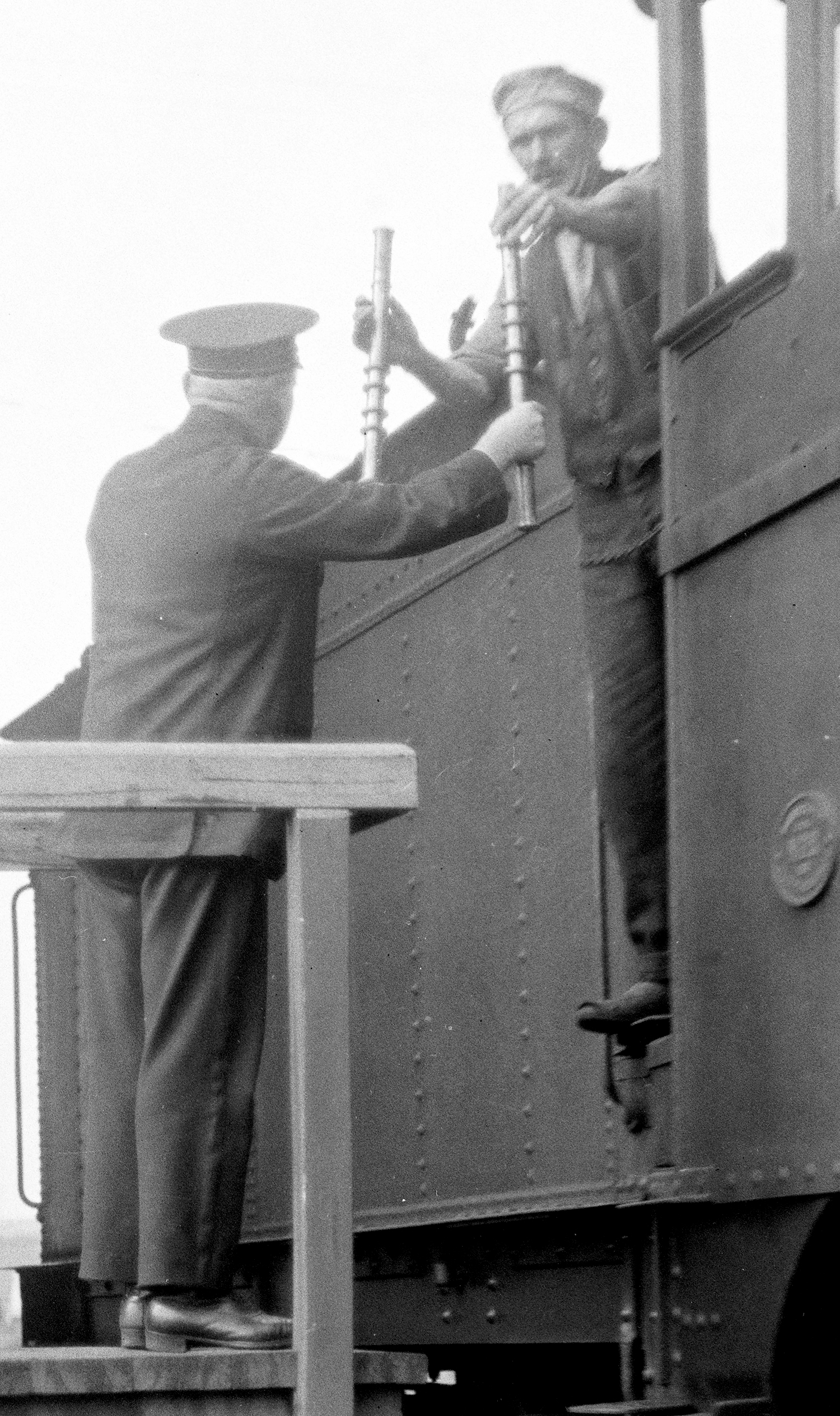
ABOVE: Hand exchanging Large Electric staffs
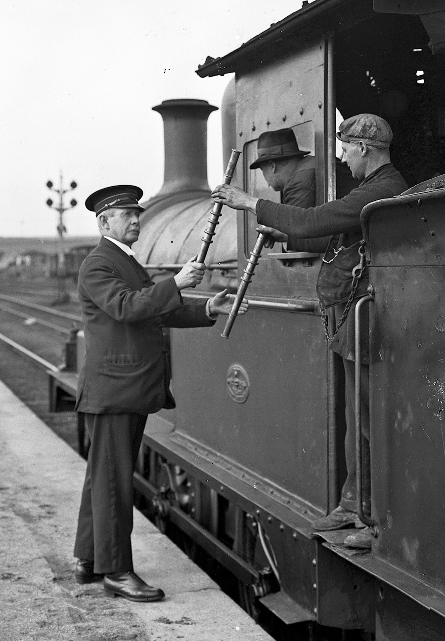
ABOVE: Hand exchanging Large Electric staffs
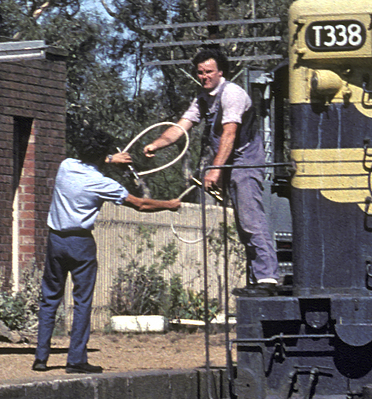
ABOVE: The author does a hand exchange of Miniature Electric Staffs at Great Western. 1981.
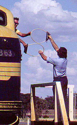
ABOVE: Hand exchange of Miniature Electric Staffs at Salisbury loop, 1982.